Water Management
Surface and Subsurface Water
Surface Water and Stormwater
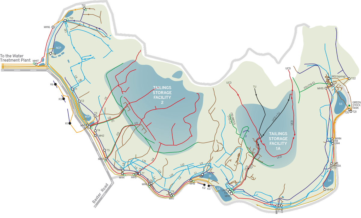
While constructing the waste rock embankments areas of bare ground are exposed and this can result in erosion and silt laden runoff. In some cases runoff from active working areas containing PAF rock has the potential for low pH. Consequently, suitable drainage interception, detention, and treatment facilities are required to minimise the effects on surrounding watercourses.
These facilities include:
- upstream diversion drains, which divert clean runoff from above the tailings storage facilities
- perimeter drains, associated with the perimeter road that enclose the construction area, to direct water to collection and silt ponds
- collection ponds, that store runoff from the embankment that can contain potentially low pH water arising from PAF material
- silt ponds, which store runoff for a sufficient time to allow any silt to be removed by gravity settling
- pumping facilities to pump stored runoff from the collection ponds to the water treatment plant as necessary.
Subsurface Drainage
At Storage 2, an extensive network of subsurface drainage was constructed beneath the tailings pond and embankment to intercept and control seepage from the tailings and leachate from the embankment, as well as naturally occurring groundwater flows. A similar under-drainage system has been constructed for Storage 1A. The drains include:
- Tailings under-drains, located beneath the tailings, that intercept downward seepage from the tailings and shallow groundwater flow
- Upstream cutoff drain, incorporated in the upstream side of zone B at foundation level that functions to intercept tailings seepage and shallow groundwater flow
- Initial toe drain, located along the downstream toe of the initial (first stage) of the embankments that intercepts seepage through the surficial soils or bedrock beneath the initial embankment
- Toe drain, located along the downstream toe of the completed embankments: this drain is in contact with bedrock and functions to intercept shallow seepage through the surficial soils and upward rising groundwater flow through the bedrock
- Gully drains located along the centreline of gullies that underlie the embankments, that intercept any seepage from the embankments as well as groundwater seepage; they also initially assist in draining and consolidating any alluvium left in place in the foundations
- Leachate drains that collect seepage from the PAF rock-fill zones within the embankments during construction, and after closure, from the bulk fill zone.
All drains connect to a series of sumps located around the perimeter of the embankments, where flows can be measured and samples taken for chemical testing. The combined under-drainage water is either sent to the water treatment plant, or recycled through the processing plant.

UNDER THE TSFs: The drainage network constructed under and within our existing TSF structures.
Water Movement through the Embankments
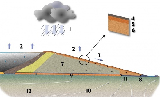
During and after a rainfall event (1), a number of processes occur:
- evapotranspiration (2) removes water directly from the soil by evaporation, and indirectly from the soil through plants by transpiration. In summer, when evapotranspiration processes are strong, water can be drawn out of the topsoil (4) and Zone H (5) as the soil dries
- runoff (3) develops when the rainfall rate is greater than the infiltration rate of the soil
- water will move quite quickly into the topsoil, but where the permeability reduces at the contact of the topsoil with Zone H, the rate of infiltration will slow down. The topsoil will become more saturated and more rainfall will run off the surface
- if rainfall continues, water will infiltrate Zone H. Where water reaches the contact with Zone G (6) (the oxygen and water control layer) the infiltration rate will again be slowed due to the lower permeability of Zone G. A head of water will begin to build at the base of Zone H on top of Zone G and movement of water downslope across the top of Zone G will develop
- water which enters Zone G will move slowly, both through this zone and also horizontally back towards the contact of Zone G and Zone H. This is because Zone G is constructed in 250 mm lifts, and the compacted layers result in lower vertical permeability than horizontal permeability. The slow movement through zone G stops air moving into the underlying PAF rock. This is the principal long term control of acid generation
- similarly, the stratification, or layering, within Zone D (7) provides preferential movement towards the downstream face of the embankments where water will be collected and diverted into the leachate drain (8)
- zone A is constructed of selected NAF material to provide a low permeability liner beneath the waste materials. The purpose of zone A is to restrict seepage to natural ground and to divert seepage to the leachate drains. It also serves to reduce upflowing groundwater from moving into the PAF rock in the embankments. The soils which are used to construct zone A have a capacity to adsorb chemical components from the leachate. This provides additional control to seepage movement
- the ash soils underlying Zone A (9) are relatively permeable and will act as an underdrain diverting any seepage through Zone A and upward rising groundwater (10) to the gully and toe drains (11)
- the weathered surface of the basement rock (12) has lower permeability than the ash and provides containment for water moving through the ash
- the groundwater flow pattern provides an upwards pressure through the basement weathered zone and provides an additional constraint to any downwards water movement.
Water movement through the cap
The performance of the cap as a barrier to water was evaluated using the SoilCover model. The main conclusions were:
- the waste rock cover is an effective barrier to water
- seepage through the cover, from the base of Zone G, is predicted to be very low and less than 1% of annual rainfall
- during most of the year, seepage occurs by unsaturated flow which is much less than saturated flow.
